)
)
)
)
)
 Concealing the Adapter Cable
This page contains suggestions for installing the Mini-Scanner in a Toyota Prius, model years 2001 to 2003. I assume you'll install the Mini-Scanner behind the steering wheel. Even if you don't want to use this installation method, you should read through these sections to find out how to hook up the cables.
Your Mini-Scanner package will include the following (click links to see pictures if necessary):
Please check that you have everything soon after receiving the package and contact ECROS Technology in the event of a problem.
You will need to remove the lid of the main unit during installation, so the case has not been closed up. Shipping the unit open also makes inspection easier for postal service security personnel. The four small screws will be used to close up the case, see below.
The DLC adapter cable has the same type of connector at each end but the optional serial cable has different connectors. Both use a flat (ribbon) cable that can be easily hidden under carpeting or floor mats but must be protected from severe abrasion. One edge of the ribbon cable is marked with a red or black stripe and this will help you to connect the cable correctly.
To install the Mini-Scanner in your car, you will need:
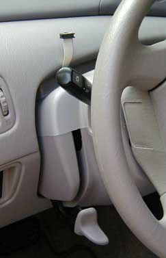
Concealing the Adapter CableFor the standard installation, the first thing to do is to pass the DLC adapter cable behind the steering wheel assembly and down behind the dash. The result is shown in the picture at right. When the upper end is connected to the Mini-Scanner and the lower end to the DLC adapter, the cable is concealed, leading to a tidy appearance. However, this is by far the most tricky part of the installation, so don't attempt this when you're hurried or in a bad mood.
Begin by releasing the steering wheel tilt mechanism. Push down the lever behind the left hand control stalk (but also see your car's User Manual for definitive instructions). Drop the steering wheel to its lowest position by pulling it down. Now there is a gap between the top of the plastic housing around the back of the steering wheel assembly and the part of the dash that curves up and forward to the windshield. If you look into this gap, it appears to be blocked at the back by a flange protruding up from the steering assembly housing. You need to get the cable into the gap, over the top of the flange and then down behind the dash into the space around the driver's feet.
Obviously, the adapter cable is not going to drop down right in the middle of the steering wheel because that's where the steering mechanism is. So, you'll have to work slightly to one side or the other. You can choose to pass the cable on either the left or the right side. I chose the left, as shown in the picture, for a number of minor reasons. The cable attaches to the main unit to the left of center, the adapter plugs into the DLC which is on the left side of the driver area (on left-hand drive cars) and the serial cable can then go on the right. However, this is the more difficult side on which to get your hand and arm up behind the dash. You will have an easier time if you have small hands or can find someone who has to help you. Failing this, everything works just fine with the adapter cable passing to the right of the steering mechanism. On right-hand drive vehicles, the DLC is to the right of the driver area. The easy and difficult sides for threading the adapter cable may also be reversed.
OK, here we go, then. Hold one end of the DLC adapter cable with the
marked edge (usually
a red stripe) to the right. The 10-pin connector on the end of the cable will be facing down. Pass the connector into the gap a few inches to one side
or the other of the center of the steering wheel, according to your choice.
 Angle the connector up (as
shown in the picture) until it clears the top of the flange and feed
the cable forward so that several inches of it disappear into the murky
depths behind the dash. Keep
the marked edge of the cable to the right. Now you will have to hold the
cable in place while you fish for the end that has disappeared and pull
it down. I found it fairly easy to reach up behind the dash from
below with one hand while holding the cable with the other. I simply groped
about in there while waving the cable to and fro and soon felt the cable
moving and was able to get a hold on it. This may work for you if
you have a good sense of where your hand is even though you can't see it and
you are physically and psychologically able to wriggle your hand up into the
innards of the car. Another approach, pioneered by someone close enough
to drive to my house to pick up his Mini-Scanner, is to fish for the cable from
below with a bent wire. This requires you to lie on your back in the driver's
foot well, but with a flashlight you have the advantage of being able to see
what you're up to.
Angle the connector up (as
shown in the picture) until it clears the top of the flange and feed
the cable forward so that several inches of it disappear into the murky
depths behind the dash. Keep
the marked edge of the cable to the right. Now you will have to hold the
cable in place while you fish for the end that has disappeared and pull
it down. I found it fairly easy to reach up behind the dash from
below with one hand while holding the cable with the other. I simply groped
about in there while waving the cable to and fro and soon felt the cable
moving and was able to get a hold on it. This may work for you if
you have a good sense of where your hand is even though you can't see it and
you are physically and psychologically able to wriggle your hand up into the
innards of the car. Another approach, pioneered by someone close enough
to drive to my house to pick up his Mini-Scanner, is to fish for the cable from
below with a bent wire. This requires you to lie on your back in the driver's
foot well, but with a flashlight you have the advantage of being able to see
what you're up to.
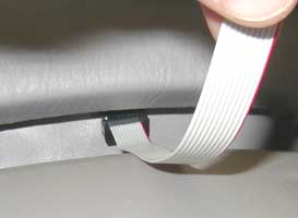
Assuming that you do somehow get hold of the cable from below, pull most of it down, leaving just a couple of inches sticking out at the top behind the steering wheel, as in the picture above. This upper end of the cable can be jiggled over into the right place to connect to the Mini-Scanner main unit later. When you are done, check that the marked edge of the cable is still to the right where it emerges at the top behind the steering wheel and that the 10-pin connector on the end of the cable faces away from you.
 The DLC adapter should next be connected to the lower end of the adapter
cable. Make sure the 10-pin connector lines up on all ten pins sticking
up from the adapter and gently push it down. The marked (red stripe) side of the cable
must be on the same side as pin 1 on the adapter. Another way to be sure
of the correct orientation is to make sure that the ribbon cable leads directly
away from the adapter board rather than folding over the top of the connector.
The DLC adapter should next be connected to the lower end of the adapter
cable. Make sure the 10-pin connector lines up on all ten pins sticking
up from the adapter and gently push it down. The marked (red stripe) side of the cable
must be on the same side as pin 1 on the adapter. Another way to be sure
of the correct orientation is to make sure that the ribbon cable leads directly
away from the adapter board rather than folding over the top of the connector.
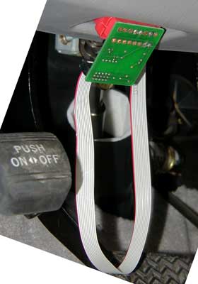
Now, plug the DLC adapter board into the Diagnostic Link Connector of the car. It will only fit one way. As you turn the adapter board to orient the connector, you will put a half-twist in the adapter cable and the marked side will now be on the left. Press the adapter board firmly behind the DLC connector to seat it. The picture at right shows the DLC adapter and cable correctly installed. The pedal in the picture marked "push on/off" is the emergency brake.
Either now or before completing the installation, you will need to tie up the slack in the adapter cable so that it does not get in the way of the driver's feet. The standard cable at 30 inches allows a little extra length for ease of installation. This results in a loop falling in front of the pedals as the picture shows. Tie this up with a twist-tie or in some other convenient way. Don't tie it up so that the cable is tight, just so that it doesn't hang down. You will need a little slack to install the main unit.
If at this point you're wondering whether the adapter will get in the driver's way, let me assure you that it has never got in my way. In fact, so that any problems in this area are likely to happen to me first, I have not tied up the slack in the cable (but please do this yourself). Not once have I kicked the adapter or the cable while driving or getting into or out of the car.
If you have the optional serial cable and you want to use it primarily for logging to a computer, you may want to install it in the car alongside the DLC adapter cable. Instructions for connecting the serial cable to the Mini-Scanner main unit are published separately. You can conceal the cable behind the dash. Threading the DB9 connector through the gap above the lowered steering wheel is made more difficult by its larger size, but easier by its weight, which makes it find its way down more readily. I accomplished this on the right hand side of the steering wheel in just a few minutes. You may have to get creative if you have trouble, perhaps threading something else through and pulling the smaller ten-pin header end upwards. Once the cable is threaded, you can route it where you want, for example over to the passenger side. Be very careful to tie it up so it cannot snag on the driver's feet.
Hold the main unit horizontally (flat) with the buttons facing away from you and lift off the top of the case by gently pulling it up. The end panels are loose, so be careful to keep them in place in the bottom half of the case. Locate the ten-pin header to which the adapter cable must be connected. It is slightly to the left of the middle on the opposite side from the buttons and is labelled JP3 on the printed circuit board silkscreen. At the far right, there is another similar header, JP4, which is for the serial cable, not the adapter cable. Move the main unit into position behind the steering wheel. Place the connector on the end of the adapter cable over all ten pins of JP3 and gently push it home. The marked side of the cable must be to the right, on the side of pin 1 as marked on the printed circuit board. As with the DLC adapter, the cable leads directly down and away from the board and does not fold over the top of the connector.
Replace the top of the main unit case, guiding the end panels into their slots. Open the packet of screws. Lean the main unit towards you, on its face, until the back is facing up. You will see the four holes into which the screws must go. Drive home the top two screws, which are now closest to you, with a small (#1) Phillips screwdriver. If you are not going to fix the unit in place with a bracket trapped by the steering wheel, drive home all four screws, tip the main unit back up and fix it by whatever method you prefer.
 I
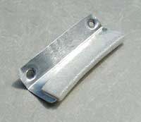
secured my Mini-Scanner using a small bracket made from a scrap of aluminum
flashing (see picture at right). Cut the flashing to size (you can use
scissors) and drill two holes the same distance apart as the bottom two screws
in the case. Put a bend below these holes, the distance depending on how
high you want the unit to sit above the steering wheel housing and the position
in which you lock the steering wheel. The bracket shown in the picture
holds the Mini-Scanner tight on the housing when the steering wheel is all the
way up. The bend should be much less than a right-angle, but you can adjust
it later. Trim the part without the holes so that it will fit into
the gap without fouling on the flange at the back. Now, you need to pad
this part of the bracket so that it will be gripped between the steering wheel
housing and the dash. How much padding you need will depend on where you
lock the steering wheel. Since I have the wheel all the way up, I
do not need much padding. I put a strip of double sided self-adhesive
foam tape on each side and then wrapped some thin foam packing material over
the edge. With my fingers, I then put a gentle curve in the bracket to
match the top of the housing. Before fixing the bracket to the back of
the main unit, you need to put some dents around the holes so that the heads
of the screws will go into these depressions. Otherwise, the screws
will not be long enough, although you could use longer screws. I did this
with a centerpunch and hammer, placing the bracket on the end of a scrap of
soft wood to act as a cushion. Place the bracket over the holes for the
bottom screws and drive the screws home. Tip the main unit back up to
the vertical position and move it back towards the dash so that the bracket
enters the gap above the steering wheel housing. The cable(s) should pass
underneath the bracket. Make sure they are lying flat and are not folded
or strained. Push any spare cable back behind the dash. Holding
the unit in your left hand, center it on the steering wheel. With
your right hand, raise the steering wheel to its usual position and check that
it grips the bracket. Adjust the padding on the bracket to achieve a satisfactory
grip. Holding the steering wheel up with your right hand, lock it into place
with your left. Check that cables falling below the dash are out of the
way of the driver's feet. You are now ready to try out your Mini-Scanner!
I
secured my Mini-Scanner using a small bracket made from a scrap of aluminum
flashing (see picture at right). Cut the flashing to size (you can use
scissors) and drill two holes the same distance apart as the bottom two screws
in the case. Put a bend below these holes, the distance depending on how
high you want the unit to sit above the steering wheel housing and the position
in which you lock the steering wheel. The bracket shown in the picture
holds the Mini-Scanner tight on the housing when the steering wheel is all the
way up. The bend should be much less than a right-angle, but you can adjust
it later. Trim the part without the holes so that it will fit into
the gap without fouling on the flange at the back. Now, you need to pad
this part of the bracket so that it will be gripped between the steering wheel
housing and the dash. How much padding you need will depend on where you
lock the steering wheel. Since I have the wheel all the way up, I
do not need much padding. I put a strip of double sided self-adhesive
foam tape on each side and then wrapped some thin foam packing material over
the edge. With my fingers, I then put a gentle curve in the bracket to
match the top of the housing. Before fixing the bracket to the back of
the main unit, you need to put some dents around the holes so that the heads
of the screws will go into these depressions. Otherwise, the screws
will not be long enough, although you could use longer screws. I did this
with a centerpunch and hammer, placing the bracket on the end of a scrap of
soft wood to act as a cushion. Place the bracket over the holes for the
bottom screws and drive the screws home. Tip the main unit back up to
the vertical position and move it back towards the dash so that the bracket
enters the gap above the steering wheel housing. The cable(s) should pass
underneath the bracket. Make sure they are lying flat and are not folded
or strained. Push any spare cable back behind the dash. Holding
the unit in your left hand, center it on the steering wheel. With
your right hand, raise the steering wheel to its usual position and check that
it grips the bracket. Adjust the padding on the bracket to achieve a satisfactory
grip. Holding the steering wheel up with your right hand, lock it into place
with your left. Check that cables falling below the dash are out of the
way of the driver's feet. You are now ready to try out your Mini-Scanner!
For the Mini-Scanner to communicate with the car, the car must be turned on, although it need not actually be started. To turn the Mini-Scanner on, press the On/Reset button, which is on the far left. The Mini-Scanner will send messages to the car and begin displaying information obtained from the car's ECUs (Electronic Control Units). If it does not receive a response from the car, it will display a diagnostic message and turn itself off. The most likely cause of this is that the car is not turned on. Turn the car on and try again. You can press the On/Reset button to restart the Mini-Scanner at any time. It is not necessary to wait for it to turn itself off.
The Mini-Scanner turns itself off soon after you turn the car off. It does this by noticing that the car has stopped responding to requests for information. A message to this effect will be displayed for a few seconds before the unit actually powers off. (If this message appears while the car is on, a problem has developed.) Should you ever find that the Mini-Scanner does not turn itself off when the car is turned off, uninstall it at once and contact ECROS Technology to arrange for repair. If you want to turn the unit off while the car is still turned on, press all three of the Left, Middle and Right buttons simultaneously.
Detailed instructions on operating the Mini-Scanner are published separately in the User Manual.
To take advantage of new releases of Mini-Scanner firmware, obtain a new firmware file and follow the procedure described in the description of the Flash Loader.
The Mini-Scanner has been designed so that you can leave it installed in your car whenever you wish. When it is off, it takes no power from the car and will not contribute to battery drain. There will be times, however, when you want to uninstall the Mini-Scanner either completely or partially. For example, the DLC adapter must be unplugged in order for a diagnostic tester to be connected to the car. Your dealer's service department may want to connect a tester and a technician performing emissions testing will certainly need to do this. In these situations, you can simply unplug the DLC adapter from the car, but be sure not to leave it dangling in the way of the pedals. It may be a good idea not to make it obvious to technicians that you are using a scanner. If you unplug the DLC adapter from the car and from the adapter cable and take it away, there is nothing to really suggest a connection to the DLC. You could also disconnect and remove the main unit if you think a technician might guess what is going on. Of course, you could also remove the cable and leave no evidence at all (depending on how easy or difficult you found the installation of the cable!).
Should you decide to remove the main unit from the car, for example for a firmware upload, it is perfectly safe to leave the DLC adapter and cable plugged in. You can drive the car in this state. It is also safe to have the DLC adapter plugged in without the adapter cable attached. The Mini-Scanner has been designed not to present the risk of damage to your car.
Last edited November 1, 2003. All material Copyright © 2003 Graham Davies. No liability accepted.