 Who
Should Perform the Modification?
Who
Should Perform the Modification?I appear to have made the original Mini-Scanner hardware design a bit over-eager to turn itself off. This was out of fear that it would stay on and drain someone's auxiliary battery. As a result, sometimes the Mini-Scanner turns itself off right after you turn it on. In most cases, if you try again it will come on and stay on. There has been one report of a Mini-Scanner turning itself off spontaneously. If you are having either of these problems, you can pursue the modification described here.
I would be surprised if you're even reading this if you have a Mini-Scanner that already has the modification, except perhaps out of curiosity. If the serial number of your Mini-Scanner starts out MS0102..., then you have the modification described here. You should not be having problems turning the unit on and I'd appreciate your contacting me if you are.
Who
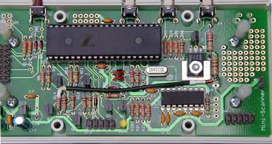
Should Perform the Modification?There is no question that this is a design defect covered under warranty and you can return the Mini-Scanner to me at my expense to be modified. However, I know that many of you are capable of making the modification yourselves and would rather do this than mess about with shipping and be without your Mini-Scanner. You may have the parts needed already or I can send them to you. So, it's up to you who performs the modification. The picture at right shows you roughly what is involved. If you try it and get stuck, I will repair your Mini-Scanner or replace the main board (within reason, so put that propane torch away).
This is what you'll need to perform the modification:
Obviously, you need to uninstall the Mini-Scanner from the car. It is also necessary to remove the display module and unscrew the PCB from the case. To ease the removal of the display, pinch together the prongs at the tops of the nylon stand-offs. The PCB is held in the case by four small sheet-metal screws very close to the bottoms of the stand-offs. Remove them with a small (#1) Phillips screwdriver, the same one you use for the case screws.
 Step 1
Remove and discard C16. This is the rightmost of the three pale blue electrolytic capacitors in the bottom left corner of the PCB. It has the value 1 µF, 25V. You can see the place it used to occupy in the picture above. If you heat up one wire at a time you can rock the capacitor up and down and after a few rocks it will fall out. As nothing goes back here, minor damage to the PCB is acceptable, but don't rip up whole traces.
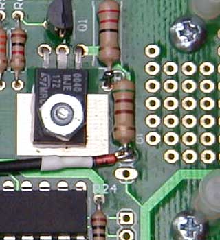
Solder a new resistor across Q2 from collector to emitter. I use a 510 ohm, 1/2 watt resistor because that's what I have. For this value, 1/4 watt would be fine. If you have 1 kohm resistors, you could use two in parallel. A lower value would be OK too, but at 390 ohms you have to step up to 1/2 watt. A side effect of this resistor's addition is that the display backlight is never entirely off, only very dim. A lower value resistor will increase the brightness. What I'm doing here is using the forward voltage drop of the LEDs in the backlight to get a voltage about four volts below the nominal 12 volt supply.
The emitter of Q2 is accessible with a convenient via, though I've filled it with solder so you'll have to suck or blow that out. Look at the bottom left corner of the prototyping area and you'll see a pair of oval vias marked JP5. The upper one of these, right by the legend "JP5", is the one you want. One leg of the resistor goes in here, as shown in the picture above/right. For the other leg, we're not so lucky as to have a hole. Unless you want to use the prototyping area and wire across underneath, I suggest you solder the other leg to the lower end of R7. This is conveniently close, half an inch more or less straight up the board. The end you want is the one right by the legend "R7". This goes to the collector of Q2. Now the backlight will get about 18 mA through this resistor (and Q2 will have to supply 18 mA less when you turn the backlight to bright). Ignore the diode and wire in the picture for now; we'll get to that in a moment.
 Step 3
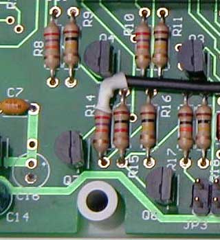
Disconnect R14 at the upper end, closest to the legend "R14". You can unsolder it if you have a de-soldering pump and can prise the lead up out of the hole. Or, if you have small side-cutters, you can snip the lead off just above the board and remove the stub or just leave it be. Note that it is important to leave enough of the lead on the resistor to attach a wire.
Now, attach a wire to the cut end of R14, as shown in the picture at right. Thread some heat-shrink tubing or other insulating sleeve down the wire so as to prevent shorts, or fix the joint in place above the board with a blob of hot-melt glue. The wire should strike off to the right, as you can see. Most of you will have a large crystal laying flat, not the small one standing up shown in the first picture. Stuffing the wire down between the crystal and C6 is a good way to hold it in place mid-travel.
In this picture, at the bottom left, you can clearly see the place where C16 has been removed. The lower pad is not as damaged as it looks. It's just burned flux, honest.
The other end of the wire added in Step 3 goes to the new resistor you added in Step 2, at the end that went into the via at JP5, through a small-signal diode. So, the first thing is to cut the wire to length. Refer back to the picture for Step 2. Leave a gap between the end of the wire and the new resistor that is a little longer than the diode body. Strip back the wire's insulation, trim the cathode lead of the diode and solder them together. Again, insulating this joint is a good idea, so use heat-shrink tubing, sleeving or a blob of glue as before.
Trim the anode lead of the diode and wrap it around the lower lead of the new resistor, as shown in the picture. Solder it carefully, being careful not to short it to the heat spreader pad under Q2.
Put the PCB back in the bottom half of the case and screw it down with the four sheet-metal screws. Position the display over the 14-pin header and press it down. It may be necessary to jiggle the stand-offs so that they go into the mounting holes. Make sure the two-pin backlight connector mates to the pins and that the polarity is correct (red to + and black to -).
The main reason I got this circuit wrong in the first place was that I'd not properly understood the Z8Encore! microcontroller brown-out detection and reset circuit. To turn off the Mini-Scanner, the microcontroller configures a port as an output and pulls it low. As the supply voltage collapses, a point will be reached where the microcontroller can no longer be expected to operate properly. I was hoping that this would be a low enough voltage that the circuit would not power up again. However, the prototypes would not turn themselves off. As soon as the supply fell to the brown-out voltage, the microcontroller resets itself, releasing the output port that's holding the supply off.
I "fixed" this with the addition of C16, which conveys the falling supply voltage to the base of the transistor, Q7, that holds the supply on, helping to keep it turned off. For me, values of 0.33 to 10 µF for C16 worked fine so I felt safe selecting 1 µF and went ahead with the production boards. This "fix" does not work as well for others as it did for me. Small dips in the car's battery voltage are probably passing through C16 and turning off the supply when it is supposed to stay on. It was a kludge anyway and I should have taken the time to find a better solution.
The basic design of the modified circuit is to remove the bias that holds Q7 on before the supply collapses to the point that triggers the microcontroller brown-out detector. So, when the microcontroller resets and the port holding the base of Q7 low lets go, there will not be enough bias from R14 to turn it back on. With a maximum brown-out voltage of 2.85 volts and a maximum drop-out across the 3.3 volt regulator of 1.7 volts, this means the bias must be removed below 4.55 volts. I suppose that fiddling with the values of R14 and R16 would have done the trick. But, to swamp the base current of Q7, the current in those resistors would have to be several milliamps at the onset of brown-out and proportionately more during normal operation. So as not to waste current, I decided to shave off some of the supply voltage with a zener diode in series with R14. This did not work because the current was too small to get the zener near its nominal voltage. Then the idea hit me of using the display backlight LEDs instead of a zener. Current here is not wasted, at least when the backlight is on and it matters. I found that a few tens of milliamps caused a drop of about 3.7 volts. So, the cathode of the backlight is this much below the supply. When the supply drops to 4.55 volts, it will be at only around a volt. This is low enough to remove the bias to Q7. I tried this and it worked. The final fix uses a diode to drop an additional half-volt or so for good measure.
As I write this, it occurs to me that the new resistor and the dim backlight are not strictly necessary after all. I could simply have turned the backlight on in firmware immediately prior to powering down. This would produce the necessary voltage drop across the backlight LEDs. However, already released versions of the firmware would not then work. I actually think the dim backlight is worth having on its own. You can just about read the display if you go into a dark tunnel without scrabbling to turn the backlight up. Also, the dim level is pretty good for unlit roads at night. Finally, peering at the backlight is a good way to be absolutely 100% sure the unit has turned itself off, if you don't trust the absence of characters.