 Here
is a link
to the schematic of the adapter board.
Here
is a link
to the schematic of the adapter board.Here you can take a look at the hardware circuit design for the Prius Mini-Scanner. You are only likely to be interested if you are an electronics engineer or hobbyist of some sort. Please note that although I am making this information public, I retain all rights to the design. I am trusting you not to swipe my work.
The Mini-Scanner DLC adapter board is attached to the back of the Data Link Connector plug and therefore lives under the dash near the driver's shins. It connects to the main unit via a 10-way ribbon cable that has a socket at each end and is therefore removable. The purpose of the adapter board is to render the signals safe to pass over a cable. It would be cheaper just to run wires directly from the DLC pins to the main unit. However, I've chosen to buffer the car's signals as close as possible to the connector. My intent is that the ribbon cable can be damaged in any way without harm to the car. No power is taken from the car unless the main unit is attached and turned on. Note that I have not isolated the scanner from the car's electrical system. Opto-isolators and an isolating DC-to-DC converter would add quite a bit to the cost and many applications of the scanner will not benefit from isolation. So, we'll have to be careful when connecting the scanner to an external computer powered from 110 VAC or the car's power outlet.
Here
is a link
to the schematic of the adapter board.
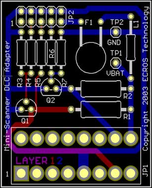
The printed circuit board layout is at right:
The board size is 1.5 by 1.8 inches. The DLC sits on the board at the bottom with the pins facing up so the whole thing sort of hangs off the plug. The part of the board with the other stuff on it is towards the front of the car, away from the driver, so it does not stick out into the driver's footwell.
JP2 (top left) is a pin header for the ribbon cable to the main unit. This cable should run further forward in the car and up behind the dash, again keeping out of the driver's way. It may be necessary to tie up the cable in some way so that it can be long enough for flexible placement of the main unit and yet not hang down near the driver's feet. I think the cable will emerge in the gap between the steering wheel housing and the dash. This is my recommended position of the main unit, so if this all works out the cable will not be visible. I haven't jet figured out how to anchor the main unit, but certainly double sided adhesive foam or Velcro™ strips will do the trick.
I have provided test points for signal ground and battery power. Hackers can use these if they need to hook anything else up to the battery. If battery power at the DLC is unswitched, as the SAE J1962 specification suggests, this would be somewhere to connect a solar charger, perhaps sitting on the top of the dash.
Everything else is in the main unit, including the On/Reset button, three programming buttons and the two line by 20 character LCD display with backlight. Here is a link to the schematic.
The power supply is at the bottom left. I need 5V for the LCD and serial port driver and 3.3V for the Z8Encore! microcontroller. Q1 turns the unit on and off. This transistor is turned on by either or both of the On/Reset switch and Q2. Q2 is biased on as soon as power is applied unless port PA2 of the microcontroller interferes. So, when you press and hold the On/Reset switch, the circuit powers up. To turn the scanner off, the microcontroller software configures PA2 as an open-drain output and sets it low, removing the bias from Q2.
Above the power supply is the interface to the car's signals at the DLC. This needs to be considered in conjunction with the adapter board. It is more complicated that other designs because a) to use the microcontroller UART, K and L must be the right way up rather than inverted, b) negligible power must be consumed when the unit is off even if it is left plugged in and c) I suspect that many published circuits don't actually comply with ISO9141. The drivers for the K and L lines are simple two-stage PNP/NPN current gain circuits with base pull-down resistors to reduce power-off leakage. The receiver for the K line is an emitter-coupled comparator with modifications. D2 blocks current when the K line is high, so the voltage divider on the left has to keep the left transistor off in this state on its own. A bit of hysteresis is applied via R3 to speed up transitions. D3 clamps the output voltage at about 4V so as not to exceed the maximum input voltage of the microcontroller. LED1 lights (albeit dimly) when the K line is low, providing some indication of bus activity. Note that to meet the ISO9141 specification, this circuit has to work at battery voltages from 8 to 16 volts and read 30% or less as low and 70% or more as high. This means, for example, that if the battery voltage is 16 volts, then an input of 4.8 volts is "low".
Moving on up the left side, we have the three programming buttons connected to port PB0, 1 and 2 of the microcontroller. This port is not 5V tolerant. Five bits are unused. The alternate function of this port is as analog inputs, so the scanner could be adapted for analog data logging. To the right is the microcontroller itself and then the pin header for the LCD. Port PC0 through 6 drives the LCD in 4-bit mode (PC7 is not pinned out in the 40 DIP version). This blocks the alternate functions timer 1, timer 2 and SPI. At the top right is the LCD backlight circuit. Q3 and Q4 make a constant-current feed to avoid distracting flicker as battery voltage changes. Having gone this far, it is trivial to have the backlight software controlled and this is done via port PD3.
Below the backlight circuit on the right is the serial port for connecting a computer or other device. The alternate function of ports PD4, 5 and 6 is used, which is to say, UART1. I have some concerns in this area. I don't think there's space for a DB9, so I've thrown in a 4-pin header. So, a custom cable is required, which increases cost, but at least you don't have to buy your own if you don't already have one. Then, there's the issue of ground being connected to the car's electrical ground, so you need to watch what you connect here. Infra-red (IRDA) might be better all round, but how would you keep a notebook in line-of-sight for logging?
To the left of the serial port, you can see the crystal oscillator for the microcontroller, below which is the port for attaching the ZiLOG debug dongle if you have their software development kit (currently a steal at $49.95). This will be useful for hackers only, but using it you could seriously customize the scanner or turn it into something else.
The adapter and the main unit are joined by a 10 conductor ribbon cable with an insulation displacement connector at each end.
A serial cable is needed if you want to connect the mini-scanner to a computer.
If you want to write your own software to run on the mini-scanner, you will need the ZiLOG software development tools for the Z8Encore! and a debug port adapter. If you buy the evaluation board, all this stuff and more comes with it. The development tools are available from ZiLOG here and a whole lot of related documentation here. I don't know whether ZiLOG intend these links to be public so that people can get this stuff for free so please don't call for technical support and tell ZiLOG I published these links. If you download the tools, you're still missing the debug adapter. There is a section in the Z8Encore! Product Specification about what is needed. The adapter in the evaluation kit differs slightly from what is shown there, however, so I have redrawn its schematic and you can see it here. What I show as a 74LS125 is actually a 74LVC1G125, which is a minuscule five-pin IC containing a single tri-state buffer. I've no idea what purpose the mystery resistor serves. Please note that on the mini-scanner I've connected pin 6 of the debug connector to GND as well as pins 3 and 5 to make the PCB layout a bit easier.